Round LCD displays bring a distinctive appearance to embedded equipment, but their shape affects much more than industrial design. Engineers must consider pixel mapping, interfaces, touch integration, optical bonding, enclosure tolerances, and software layout before committing to a module.
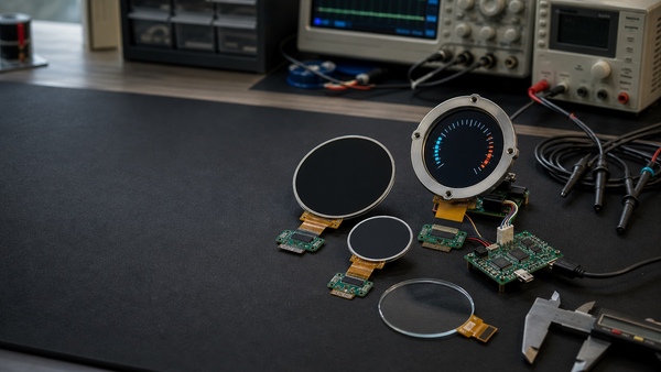
A circular display can make a product feel more like an instrument than a computer. That is why round LCD modules appear in smart thermostats, motorcycle clusters, marine controls, charging equipment, coffee machines, medical instruments, audio products, and industrial gauges.
The visual result can be excellent, particularly when the screen replaces a traditional dial. However, integrating a round panel is not the same as placing a rectangular LCD behind a circular opening. A true round display has its own pixel geometry, driver requirements, mechanical constraints, and user-interface limitations.
During early prototyping, most problems look manageable. The panel lights up, the demonstration gauge moves, and the product immediately appears more polished. Difficulties tend to emerge later, when the engineering team adds a touch panel, fits the display into the production housing, qualifies it across temperature, or tries to source the same module for several years.
What Is a Round LCD Display?
A round LCD display is a TFT liquid crystal module whose visible active area is circular. Many products use a square internal pixel matrix with corners that are physically hidden or disabled. Others are designed with a circular active region and driver configuration optimized for the shape.
The module still contains familiar LCD components: TFT glass, liquid crystal material, color filters, polarizers, driver ICs, a backlight, an FPC, and usually a supporting frame. The circular appearance changes the outline of the usable image, but the underlying electronics remain closely related to those used in conventional small TFT modules.
It is important to distinguish a true round display from a rectangular panel installed behind a round bezel. The second method can be acceptable for inexpensive equipment, but it wastes display area and often creates a deep border. A true round module normally produces a thinner and more convincing instrument-like design.
| Display approach | Advantages | Limitations |
|---|---|---|
| True round TFT LCD | Compact outline, clean appearance, efficient use of front-panel space | Fewer suppliers, specialized mechanics, and more limited replacement choices |
| Rectangular LCD behind a round opening | Broader module selection and potentially lower cost | Unused corners, larger enclosure, and possible backlight leakage |
| Round OLED | Deep black levels, wide viewing angle, no conventional backlight | Different lifetime behavior, possible burn-in, and often higher cost |
| Segmented circular LCD | Low power and excellent for fixed symbols or simple gauges | Cannot display a flexible full-color graphical interface |
Where Round Displays Work Well
The circular format is most effective when information already has a radial structure. Speed, pressure, temperature, volume, direction, progress, and motor load can all be presented naturally as arcs or rotating indicators.
A round screen also works well when a product replaces a mechanical control. A rotary encoder can be mounted around or beside the display, allowing the graphics to change with operating mode. One physical dial can then control temperature, fan speed, timers, or menu selection while the display provides immediate context.
Not every interface benefits from a circle. Long text, keyboards, tables, lists, and video are usually more efficient on a rectangular screen. Engineers should choose the shape because it supports the product interaction, not only because it makes the first prototype look unusual.
Resolution and the Circular Pixel Area
Rocktech round displays are often described by a square resolution, such as 240 × 240, 360 × 360, 390 × 390, or 480 × 480 pixels. This does not mean every pixel in the square is visible. Pixels near the corners lie outside the circular active area.
Application software should treat the screen as a circle from the beginning. Important text and controls need to remain within a safe central region. Placing a rectangular user interface on the panel and clipping its corners usually produces awkward spacing and partially hidden controls.
Higher resolution improves the appearance of curved graphics, fine gauge marks, and small fonts. It also increases framebuffer size, memory bandwidth, and interface speed. A simple controller may drive a 240 × 240 display comfortably but struggle with smooth animation on a 480 × 480 panel.
Pixel density should be considered together with viewing distance. A display mounted on a wall controller does not necessarily need the same density as a wearable screen viewed from a few centimeters away. Selecting more pixels than the application can visibly use adds software and power requirements without improving the product.
Common Electrical Interfaces
Small round LCD modules frequently use SPI, parallel RGB, or MIPI-DSI. The interface affects processor selection, achievable frame rate, PCB complexity, and software integration.
| Interface | Best suited to | Engineering considerations |
|---|---|---|
| SPI | Simple interfaces, lower resolutions, microcontroller products | Low pin count, but full-screen updates may be slow |
| 8080 or MCU parallel | Microcontrollers requiring faster updates than basic SPI | More signal lines and more complicated PCB routing |
| RGB parallel | Continuous video output from MCUs or application processors | Many pins, controlled timing, and possible EMC challenges |
| MIPI-DSI | High-resolution Linux, Android, and advanced embedded systems | Low signal count, but panel initialization and high-speed layout require care |
SPI panels often include an internal display controller and framebuffer. The host sends commands and image data into the controller. This arrangement is convenient for microcontrollers, although transferring an entire high-resolution frame may take too long for fluid animation.
MIPI-DSI is more suitable when the screen is connected to an ARM application processor running Linux or Android. It provides substantial bandwidth over a small number of differential lanes. The tradeoff is greater dependence on the panel driver, initialization command sequence, lane configuration, and board support package.
Two round panels with the same diameter and resolution are not automatically interchangeable. Their FPC pin assignments, supply voltages, driver ICs, initialization commands, and interface modes may differ. A mechanically compatible replacement can still require a PCB and software change.
Backlight Design and Power Consumption
A TFT LCD does not emit its own light. White LEDs behind the panel illuminate the liquid crystal stack. The backlight is often the largest consumer of power in the display assembly.
Small round modules may include several LEDs connected in series. A constant-current driver is normally required, and the necessary LED voltage can be higher than the system supply. The design may therefore need a boost converter rather than a simple resistor or logic-level output.
Brightness control is commonly implemented with PWM. The PWM frequency should be high enough to avoid visible flicker and camera banding but remain within the recommended range of the driver. The minimum usable brightness should also be tested; some drivers become unstable or inconsistent at very low duty cycles.
Outdoor products may require a high-brightness backlight, but luminance alone does not guarantee sunlight readability. Reflection from the cover glass and the air gap can overwhelm the image. Optical bonding and anti-reflective treatment may improve practical contrast more effectively than simply increasing LED current.
Designing a User Interface for a Circle
A round interface needs its own layout rather than a cropped rectangular design. Radial graphics look natural, but they should not be used for every value. A large numeric reading in the center is often easier to understand than a decorative needle.
The outer area is useful for status arcs, progress, scale marks, and secondary information. The central area works well for the primary value, operating mode, or a clear icon. Controls that require accurate touch input should not be placed too close to the curved edge.
Designers should establish a safe-content diameter. All essential labels and buttons remain inside this boundary, while decorative backgrounds can extend to the physical edge. The safe area must also account for mechanical tolerances between the LCD, cover lens, and enclosure opening.
Font testing deserves attention. Text that appears readable on a desktop mockup may look too small on the actual module. Anti-aliasing, subpixel arrangement, viewing distance, and cover-glass reflection change the result. Engineers should review the user interface on production-resolution hardware early in development.
Touchscreen Integration
A round capacitive touchscreen can be laminated over the display, creating a clean user interface without mechanical buttons. The touch sensor is usually connected separately through I2C or USB; display image data and touch coordinates do not normally share the same interface.
The touch sensor may be physically circular, or it may use a square sensor area hidden beneath a round cover lens. Either arrangement can work, but the active touch boundary must match the graphical interface.
Cover-glass thickness affects touch sensitivity. Glove operation, water droplets, electrical noise, and metal enclosure grounding can also change performance. Touch-controller tuning should be completed with the final glass, adhesive, LCD, power supply, and enclosure rather than on an open evaluation bench.
A circular screen encourages edge gestures and radial controls, but touch accuracy often decreases near the perimeter. Small buttons arranged tightly around the edge can frustrate users. A physical rotary encoder may be a better input method for equipment used with heavy gloves or in moving vehicles.
Optical Bonding and Cover Glass
A display can be assembled with an air gap between the LCD and cover glass, or the layers can be joined with optically clear adhesive. Air-gap construction is less expensive and can make service replacement easier. However, internal reflections reduce contrast and moisture may enter the space if the product is not sealed correctly.
Optical bonding fills the gap with transparent adhesive. It reduces internal reflection, improves perceived contrast, and supports the glass against pressure. The result is valuable for outdoor displays and products that require a premium appearance.
The process adds cost and manufacturing risk. Bubbles, dust, adhesive overflow, misalignment, yellowing, and delamination must be controlled. Circular parts can be particularly sensitive to rotational alignment when the cover glass includes printed icons or an asymmetric logo area.
The cover lens should not be specified by diameter alone. Drawings need to define glass thickness, edge treatment, decorative printing, optical coatings, openings, adhesive region, and dimensional tolerances.
Mechanical Integration
A round opening seems mechanically simple, but the display still requires careful support. The LCD frame should sit on a flat surface without point loads. A screw head, burr, or locating feature pressing against the glass can create a fracture point.
Manufacturing tolerances can shift the visible area relative to the bezel. The enclosure opening should not be designed exactly to the nominal active diameter. A small mask or overlap hides positional variation, but excessive overlap wastes pixels and can cover outer scale marks.
The FPC exit direction deserves early attention. A module may fit perfectly in the front housing while its cable points toward a wall, speaker, battery, or mounting boss. Reversing the module may rotate the display and touch coordinates, assuming the mechanical construction even allows it.
Adhesive tape and gaskets should accommodate differences in thermal expansion between glass, metal, and plastic. Tight clamping around the circumference can distort the module or produce uneven pressure. Waterproof designs require controlled gasket compression rather than simply increasing screw torque.
Temperature and Environmental Behavior
Liquid crystal response slows at low temperature. A round gauge may show visible trailing or delayed animation even though the display technically remains operational. At high temperature, backlight LEDs, polarizers, adhesives, and touch materials may age faster.
Outdoor and vehicle products should be evaluated after the entire assembly reaches thermal equilibrium. A brief room-temperature test followed by a few minutes in a chamber does not represent real operation.
Direct sunlight introduces another issue. A dark display installed behind glass can absorb significant heat, raising the internal temperature above ambient. The housing, ventilation, backlight current, and software dimming strategy all affect the final result.
Software and Graphics Performance
The software platform must render a circular interface efficiently. A microcontroller-based design may draw directly into the display controller or maintain a local framebuffer. Linux and Android systems typically use hardware-accelerated graphics and a full compositor.
Transparent layers, shadows, large image files, and constant animation can consume more processing power than expected. The application should be tested on the intended hardware, not only on a desktop development computer.
Some graphical frameworks support circular clipping, arcs, and anti-aliased vector elements efficiently. Others generate a complete rectangular frame even though the corner pixels are invisible. This does not necessarily cause a problem, but it should be included in memory and bandwidth calculations.
Screen rotation should be defined consistently across the bootloader, operating system, application, and touch driver. A correction made only in the application can leave the boot logo or recovery interface at the wrong angle.
Selecting a Round LCD Module
| Selection area | Questions to answer |
|---|---|
| Size | Does the active diameter fit the viewing distance and enclosure? |
| Resolution | Can the host render the required interface at the target frame rate? |
| Interface | Does the processor support the electrical mode and driver IC? |
| Brightness | Is the minimum finished-product luminance adequate? |
| Viewing angle | Will the display be viewed from the side or below? |
| Touch | Must it support gloves, water rejection, or thick cover glass? |
| Temperature | What happens during cold startup and extended high-temperature use? |
| Mechanics | Are the FPC position, frame, thickness, and mounting method suitable? |
| Lifecycle | How long will the exact panel and driver configuration remain available? |
Production Validation
Qualification should use the production cover glass, touch panel, FPC, host board, power supply, and enclosure. Testing a bare display module proves only a small part of the finished system.
Run repeated cold and warm starts, sleep-and-wake cycles, brightness changes, touch tests, and full-screen animation. Check for light leakage, uneven brightness, image retention, color shift, FPC stress, and touch errors near the edge.
Use samples from multiple manufacturing lots. A single engineering sample may have been carefully selected and does not show normal production variation. Pixel-defect limits, cosmetic inspection conditions, brightness tolerance, and touch acceptance criteria should be agreed with the supplier in writing.
Long-term availability is especially important because round displays have fewer direct replacements than common rectangular panels. If the internal driver IC changes, the software may need a new initialization sequence even when the module outline remains the same.
Final Engineering Perspective
A round LCD can give an embedded product a strong identity and make instrument-style information easier to understand. Its value is greatest when the physical shape and user interface support the same interaction.
The shape also reduces flexibility. Content space is limited, mechanical alignment is more visible, and alternative modules may be difficult to source. Successful integration requires more than selecting a diameter and resolution.
Engineers should evaluate the display, interface, backlight, touch sensor, cover glass, enclosure, and software as one assembly. The best round display is not necessarily the panel with the highest resolution or brightness. It is the module that fits the mechanical design, remains readable in the real environment, responds reliably to the intended controls, and can still be purchased throughout the product’s service life.
下一則: Smart Control Panels for Embedded Products: What Engineers Should Check Before Production
限會員,要發表迴響,請先登入


