Design points and maintenance measures for stepper motor encoders
2025/04/18 17:18
瀏覽122
迴響0
推薦0
引用0
1. Definition and function of stepper motor encoders
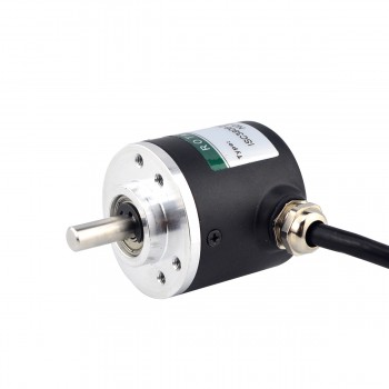
A stepper motor encoder is a digital type of direct drive motor whose position and speed can be controlled by applying digital pulses. The encoder is a sensor used to measure parameters such as position, angle and linear velocity. Through data interaction and parameter feedback, the stability and reliability of the system are guaranteed. The stepper motor encoder is used in combination with the stepper motor to achieve high-precision position measurement and control, as well as efficient and stable motion control.
2. Main classifications of stepper motor encoders
1. Incremental encoders work on the principle of photoelectric conversion and output three sets of square wave pulses: A, B and Z phases. There is a 90° phase difference between the A and B pulses, which is used to determine the direction of rotation; the Z phase outputs one pulse per revolution to provide a reference point positioning function. The advantages of incremental encoders include simple structure, long mechanical life, strong anti-interference ability and high reliability, which are suitable for long-distance transmission applications, but their limitation is that they cannot directly output the absolute position information of the shaft rotation.
2. Absolute encoders directly output digital quantities. Their working principle is to alternately arrange the light-transmitting and light-opaque sectors on the circular code disk. When the code disk is in different positions, the photosensitive element converts the corresponding level signal according to whether it is illuminated to form a binary digital number. This encoder can provide accurate position, angle and number of turns information, and is suitable for application scenarios that require high-precision measurement.
3. Design points of stepper motor encoders
1. Resolution and accuracy: The resolution of the encoder determines the minimum change in the motor position that it can detect. High-resolution encoders can provide more precise control, but may also increase the complexity and cost of the system. Accuracy refers to the degree of conformity between the encoder output signal and the actual motor position. High-precision encoders can provide more accurate feedback information, thereby improving the performance of the control system.
2. Durability and reliability: The encoder needs to operate stably for a long time in a harsh working environment, so it is very important to choose durable materials and design reliable circuits. Durable materials and designs can ensure that the encoder can work stably in various environments.
3. Sensor type selection: Select the appropriate type of sensor according to specific application requirements. Photoelectric sensors generally have higher accuracy and resolution, while magnetic sensors are more suitable for harsh environmental conditions.
4. Circuit design optimization: Ensure that the encoder circuit design is simple and efficient, and take into account electromagnetic compatibility (EMC) issues to reduce interference and improve signal quality.
5. Testing and verification: It is very important to fully test the encoder in actual applications, including performance testing, durability testing under different environmental conditions, and compatibility testing with other system components.
6. Feedback control link: Appropriately increasing the feedback control link can improve the control accuracy and stability of the stepper motor. The feedback control link can achieve precise position control and speed control.
4. Maintenance methods for stepper motor encoders
1. Regular cleaning and dust prevention: Use a dust-free cloth or soft brush to regularly clean the encoder surface and vents to prevent dust accumulation from affecting the sensitivity of the photoelectric sensor. For open encoders, check whether the grating disk is contaminated or scratched every quarter, and wipe it with anhydrous alcohol if necessary (power off operation). The closed encoder can pass the sealing inspection. If oil infiltration is found, the sealing ring needs to be replaced.
2. Check the connection and signal stability: Check the encoder connection cable for looseness, damage or excessive bending every month, use a multimeter to test the continuity, and focus on checking the plug oxidation or poor contact. It is recommended to use shielded cables and arrange them reasonably to reduce the impact of electromagnetic interference on pulse signals.
3. Power supply and grounding verification: Regularly measure the encoder supply voltage to ensure that it is within the rated range (such as 5V±5%), check whether the grounding resistance is less than 1Ω, and eliminate common mode interference.
4. Mechanical structure and installation status maintenance: Check the encoder bearing for abnormal noise or jamming every six months, and add special grease. For encoders with gear transmission, check the wear of the tooth surface. If the wear exceeds 30%, the gear set needs to be replaced. Check the connection screws between the encoder and the motor shaft every week to see if they are loose, and use a torque wrench to tighten them according to the manual requirements. Combined with the laser alignment instrument, calibrate the mechanical shaft alignment every quarter to reduce the offset of the code disk caused by eccentricity.
5. Performance calibration and parameter verification: Zero calibration: When the encoder fails, the encoder is replaced, or the electrical zero position of the encoder does not coincide with the mechanical zero position, the encoder needs to be zero-point calibrated. The incremental encoder needs to monitor the Z-phase signal through an oscilloscope to ensure that the zero point is aligned with the motor pole; the absolute encoder needs to be calibrated once for the entire stroke. When using the built-in calibration function of the servo drive, the load must be separated and no-load zeroing must be performed.
6. Dynamic performance test: Simulate load operation every quarter to observe the waveform stability of the encoder feedback signal. Abnormal jitter or pulse loss may indicate aging of internal components.
7. Optimization of environment and use conditions: Pay attention to changes in the temperature and humidity environment during the use of the encoder, and ensure that the ambient temperature is between -10℃ and 60℃ and the humidity is less than 85%. In high temperature environments, heat sinks or forced air cooling can be installed to prevent the encoder temperature from rising by more than 15℃. Install a shock-absorbing bracket near the vibration source to control the amplitude to less than 0.1mm.
自訂分類:不分類
上一則: What are the installation precautions for helical planetary gearboxes?下一則: Working principle and design requirements of worm gear reducer gearbox
你可能會有興趣的文章:
- How a Pancake Stepper Motor Works and its Applications
- How to maintain an integrated stepper motor?
- Working principle and design requirements of worm gear reducer gearbox
- Main advantages and selection criteria of servo motors
- Characteristics and application fields of DC gear motors
- Some important information about stepper motor encoders
限會員,要發表迴響,請先登入


